

Clamper circuits shift a signal's voltage level without changing the shape of its waveform.
- Add a DC level to an AC signal, shifting the entire waveform up or down by an amount set by an independent voltage source.
- Built using diodes, capacitors, and sometimes resistors; also known as DC restorers or clamped capacitors.
Types of Clamper Circuits
Clamper circuits come in a few common varieties, each suited to different applications.
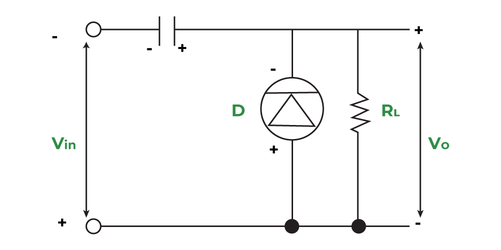
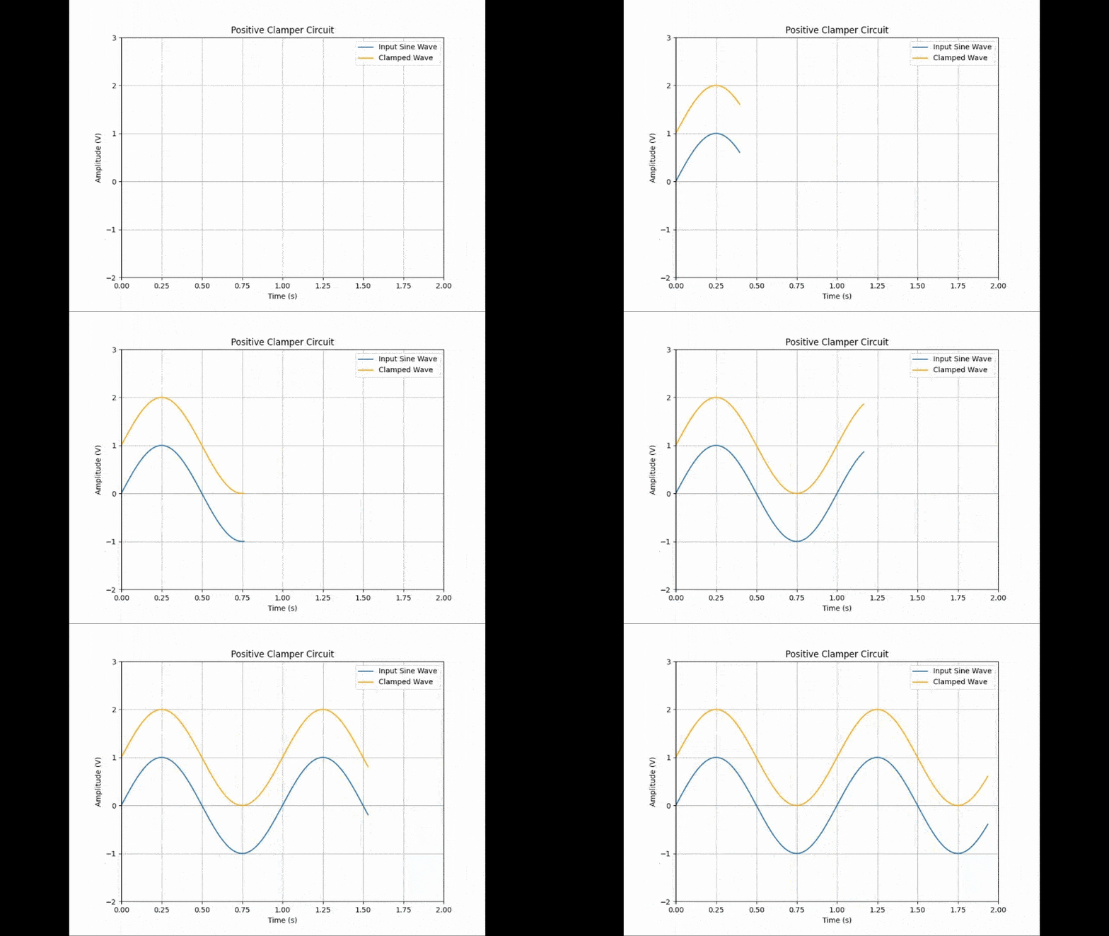
- Positive clampers: shift the input signal above the zero level, to the +ve DC level.
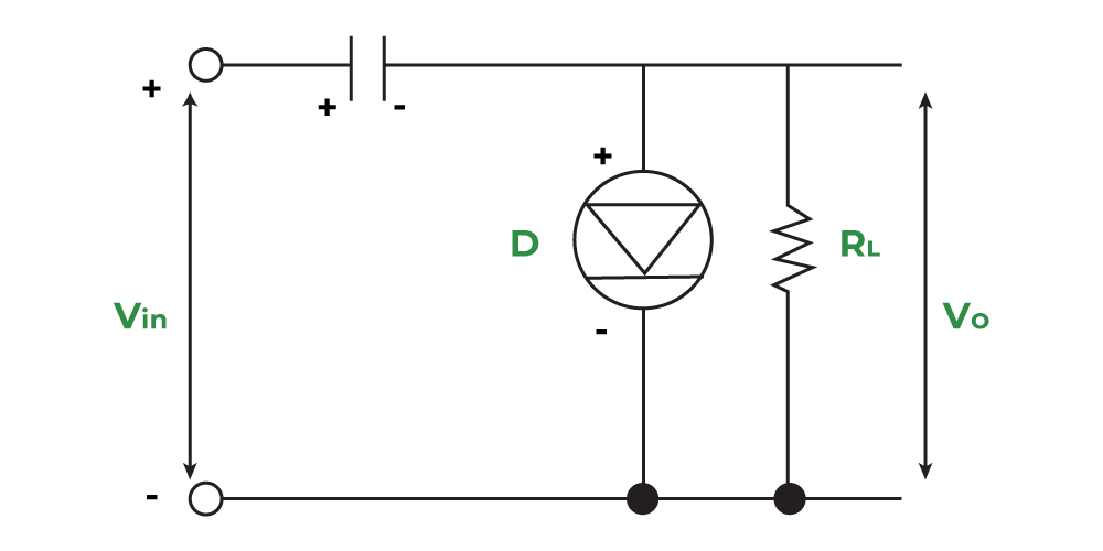
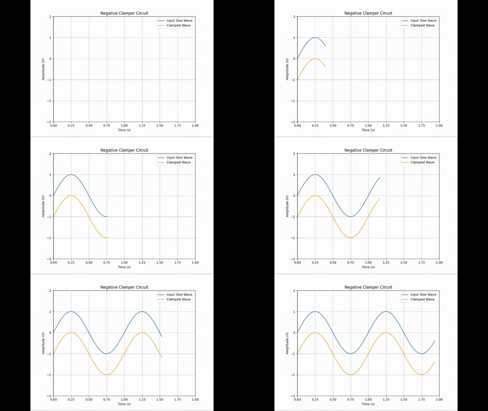
- Negative clampers: shift the input signal below the zero level, to the -ve DC level.
- Biased clampers: shift the waveform above or below a DC reference other than 0 V, using a voltage source and resistor to set the offset. The offset equals the supplied voltage plus the diode's forward voltage drop (0.7 V for a Si diode), with the clamper type (positive or negative) determining the direction of the shift.
Working Principle of Clamper Circuits
Clamper circuits work by charging a capacitor to the peak value of the input signal during one half of the waveform cycle. The diode controls current flow direction, charging the capacitor, and the stored charge then shifts the waveform up or down depending on the clamper's configuration.
Positive Clampers
- During the negative half-cycle, the diode is forward biased and conducts like a short circuit, so Vo → 0 V. The capacitor charges to the peak input value Vm and behaves like a battery.
- During the positive half-cycle, the diode becomes reverse biased and acts as an open circuit. The capacitor can only discharge through R(load); since R(load) is high resistance, it discharges very little each cycle.
Applying KVL across the loop (at maximum positive input, Vin = +Vm):
Vi + Vm - Vout = 0
This gives the output voltage:
Vout = Vin(peak) +Vm = Vm + Vm
Vo = 2Vm (positive clamp voltage)
Negative Clampers
During the positive half-cycle, the diode is forward biased, conducts, and acts like a short circuit. The capacitor charges to the peak value of input Vm and behaves like a battery.
- During this interval, the output Vo, taken across the short circuit, is zero.
- During the negative half cycle, the diode does not conduct and acts as an open circuit.
The output voltage can be found by applying KVL (at maximum negative input, Vin = -Vm):
Vm - Vm - Vo = 0
Vo = -2Vm
Mathematical Representation
The output of a clamper circuit can be expressed as:
Vout(t) = Vin(t) + Vshift
Where:
- Vout(t) → output voltage at time t
- Vin(t) → input voltage at time t
- Vshift → the voltage shift introduced by the clamper, determined by the capacitor and diode configuration
Output Waveforms
Different circuits produce different output waveforms depending on the type of clamping or rectification applied to the input signal.
Half-Wave Rectified Sine Wave
Half Wave rectifier sine wave is produced by applying a half-wave rectifier to a sine wave, resulting in a waveform with only positive (or only negative) peaks.

Full-Wave Rectified Wave
Full Wave Rectifier is achieved using a full-wave rectifier, which converts both halves of the input into a fully positive (or fully negative) waveform.

Advantages
- Signal conditioning: Prepares analog signals for digital conversion or further processing.
- Voltage regulation: Keeps voltage levels steady by clamping signals to a fixed reference.
- Protection: Prevents high voltage spikes from damaging sensitive components.
Disadvantages
- Component dependency: Performance depends on the quality of the capacitor and diode used.
- Design complexity: Biased clampers need accurate DC biasing, which can complicate the design.
- Possible distortion: An incorrectly adjusted clamper can distort the output signal.
Applications of Clampers
- Signal conditioning: Preparing signals for conversion or additional processing.
- Voltage regulation: Keeping power supply voltage levels stable.
- Protection circuits: Guarding components against voltage spikes.
- Power supplies: Regulating the amplitude and waveform shape in converters.
