

Both the input and output circuits share a collector terminal. The emitter and collector receive the output signal, whereas the base and collector receive the input signal.
- Because the output voltage at the emitter follows the input voltage applied at the base, the common collector amplifier is sometimes referred to as an Emitter Follower.
- Impedance matching applications can benefit from this configuration's high input impedance and low output impedance.
Circuit Diagram
In a common collector amplifier circuit:
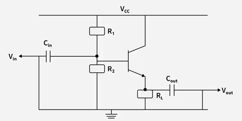
- The collector terminal serves as the common reference point and is often connected to the supply voltage.
- A coupling capacitor is used to apply the input signal to the base terminal.
- The emitter terminal provides the output signal.
- The circuit is stabilized and biased by a resistor attached to the emitter.
- Small changes in the input signal result in matching changes in the output signal because the transistor functions in the active area.
Working Principle
The following describes how the common collector amplifier operates:
- The base terminal receives a little AC input signal.
- The input signal determines how the base current varies.
- The emitter current changes in proportion to this.
- A voltage is created across the emitter resistor as the emitter current passes through it.
- The output signal is the voltage across the emitter resistor.
- The output signal's amplitude is about equal to the input voltage and it is in phase with the input signal.
Input Impedance
The ratio of input voltage to input current is known as the input impedance.
Because of its extremely high input impedance, a common collector amplifier may accept signals from sources with high resistance without loading them.
Output Impedance
The ratio of output voltage to output current when the input source is turned off is known as the output impedance.
A CC amplifier can efficiently drive low-resistance loads because of its extremely low output impedance.
Voltage Gain
The ratio of output voltage to input voltage is known as voltage gain.
The output voltage of a common collector amplifier closely tracks the input voltage since the voltage gain is about equal to 1.
Advantages
- High Input Impedance: Enables the amplifier to receive signals from sources with high resistance without experiencing a lot of loading.
- Low Output Impedance: Makes it possible for the amplifier to efficiently drive loads with low resistance.
- No Phase Inversion: The output signal is in phase with the input signal.
- Good Impedance Matching: Suitable for connecting circuits with different impedance levels.
Disadvantages
- Voltage Gain Near Unity: Offers minimal or nonexistent voltage amplification.
- Limited Power Gain Compared to CE: The power gain is lower than that of common emitter amplifiers.
- Unsuitable for Voltage Amplification: Primarily utilized for buffering instead of voltage amplification.
Applications
- Impedance Matching Circuits: Used to connect high-impedance sources to low-impedance loads.
- Buffer Amplifiers: Used to isolate two stages of a circuit without affecting signal strength.
- Signal Coupling Between Stages: Facilitates effective signal transfer between amplifier stages.
- Output Stages of Amplifiers: Often used in the output stage to drive loads such as speakers.
