

One popular technique for analyzing BJT amplifier circuits is the hybrid h-parameter model. In this method, the transistor is treated as a two-port network, where the base–emitter terminals form the input port and the collector–emitter terminals form the output port.
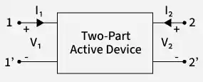
- The behavior of the transistor is described using hybrid parameters (h-parameters), which relate the input voltage and output current to the input current and output voltage.
- These parameters are called hybrid because they combine different electrical quantities such as resistance, gain, and admittance.
- This model simplifies the analysis of transistor amplifiers and can be applied to common emitter (CE), common base (CB), and common collector (CC) configurations.
Two-Port Network Representation
A transistor amplifier can be represented as a two-port network with the following variables:
V_1 : Input voltageI_1 : Input currentV_2 : Output voltageI_2 : Output current
If input current
These equations describe the electrical relationship between the input and output of the transistor.
Definition of Hybrid Parameters
The four h-parameters are defined as follows.
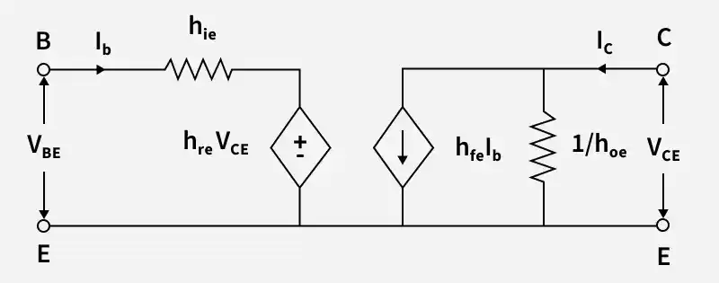
Input Impedance Parameter (
It represents the input resistance of the transistor when the output is short-circuited.
Reverse Voltage Gain (
It represents the reverse voltage gain, showing how much the output voltage affects the input voltage.
Forward Current Gain (
It represents the forward current gain of the transistor.
Output Admittance (
It represents the output conductance of the transistor when the input port is open.
Analysis of BJT Amplifier Using the Hybrid Model
When a BJT amplifier is analyzed using the hybrid model, the circuit includes:
- Source resistance
R_s - Load impedance
Z_L - Input impedance
Z_{in}
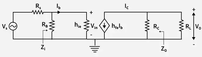
Using the h-parameter model, several amplifier characteristics can be determined.
Current Gain
The ratio of output current to input current.
For the hybrid model,
where:
A_I : Current gainh_f : Forward current gain parameterh_o : Output admittance parameterZ_L : Load impedance.
Input Impedance
Ratio of the input voltage to the input current of the amplifier.
It depends on the input parameter
Voltage Gain
Ratio of output voltage to input voltage.
For the hybrid model, the voltage gain depends on the forward current gain, input resistance, and load resistance.
Voltage Gain Considering Source Resistance
When the source resistance
Current Gain Considering Source Resistance
Using Norton’s equivalent circuit, the effective current gain becomes
Output Impedance
Ratio of output voltage to output current when the input source is deactivated.
Analysis of a CE Transistor Amplifier Using h-Parameters
Consider a common emitter amplifier with self-biasing.
During AC analysis:
- There is a short circuit in the DC supply
V_{CC} . - Bypass and coupling capacitors function as short circuits.
- The h-parameter equivalent model of the transistor is used in its stead.
Using the simplified hybrid model, the amplifier parameters are obtained.
Input Impedance
where
and,
-
R_B : Equivalent base resistance formed byR_1 andR_2 in parallel R_1, R_2 : Biasing resistors used to set the base voltageh_{ie} : Input resistance of the transistor in common emitter configuration
Output Impedance
where,
R_C : Collector resistor connected in the collector circuitZ_o : Output impedance of the amplifier
Voltage Gain
where
h_{fe} : Forward current gain of the transistor in CE configurationR_C : Collector resistor connected in the collector circuitR_L : Load resistance connected at the output of the amplifierh_{ie} : Input resistance of the transistor in common emitter configuration
Current Gain
Analysis of CE Transistor with Unbypassed Emitter Resistance R_E
If the emitter bypass capacitor
Effects of Unbypassed
- Input resistance increases
- Voltage gain decreases
- Output impedance remains approximately the same
The input impedance becomes
The voltage gain becomes
Hybrid Parameters for Different Configurations
Hybrid parameters vary depending on the transistor configuration.
Common Emitter (CE)
- High current gain
- Moderate input resistance
- Moderate output resistance
Common Collector (CC)
- High input resistance
- Low output resistance
- Voltage gain approximately equal to unity
Common Base (CB)
- Low input resistance
- High output resistance
- High voltage gain but current gain less than unity
Advantages
- Simple Analysis: Offers a straightforward approach to transistor amplifier circuit analysis.
- Applicable to Various Configurations: CE, CB, and CC amplifier configurations can all make use of the same model.
- Experimentally Measurable Parameters: Direct experimental measurements can yield h-parameters.
- Appropriate for Low-Frequency Analysis: Excellent for examining transistor amplifiers operating at low frequencies.
Disadvantages
- Unsuitable for High Frequencies: When analyzing high-frequency amplifiers, accuracy declines.
- Parameter Variation: Temperature and biasing are two examples of operational circumstances that affect h-parameter values.
- Complex Circuit Equations: Complicated circuit equations might result from in-depth investigation.
