

Electronic systems often need to process weak signals before they can be used in practical applications. Signals produced by sensors, microphones, or communication circuits are usually very small in magnitude and must be strengthened before further processing. This is achieved using amplifiers.
- A BJT amplifier uses a Bipolar Junction Transistor (BJT) to increase the amplitude of an input signal.
- The transistor takes a small input signal and produces a larger output signal by drawing energy from a DC power supply.
- Amplifiers are widely used in audio systems, communication devices, instrumentation circuits, and many other electronic applications.
Amplifier
An electronic device that increases the voltage, current, or power of an input signal without significantly changing its waveform.
- In practical circuits, the amplification process is performed using active devices such as transistors or operational amplifiers.
- When a transistor is used as the active element, the circuit is called a transistor amplifier.
- The transistor does not create energy by itself. Instead, it controls the flow of energy from the DC power supply, allowing a small input signal to produce a much larger output signal.
Block Diagram of an Amplifier
A basic amplifier can be represented using a block diagram that shows how signals flow through the system.
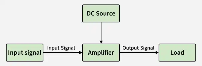
Components
- Input Signal: The input signal is a weak electrical signal that needs to be amplified. It may come from sources such as microphones, sensors, antennas, or other electronic circuits.
- Amplifier: The amplifier is the main circuit that increases the strength of the input signal. In BJT amplifiers, this function is performed by a Bipolar Junction Transistor operating in the active region.
- DC Power Supply: The amplifier requires a DC power source to provide energy for amplification. The transistor uses this supply to increase the magnitude of the signal.
- Output Signal: The output signal is the amplified version of the input signal. Ideally, it should have the same shape as the input waveform but with greater amplitude.
- Load: The load is the device or circuit that receives the amplified signal. Examples include speakers, communication circuits, or measurement devices.
Working
- The operation of a BJT amplifier can be summarized in the following steps:
- A small AC input signal is applied to the base terminal.
- This signal causes a small variation in base current.
- Due to transistor action, a much larger variation occurs in the collector current.
- The collector current flows through a load resistor, producing a larger output voltage.
- The output signal becomes an amplified version of the input signal.
Thus, the transistor effectively converts a small input signal into a larger output signal.
Role of BJT in Amplification
A Bipolar Junction Transistor (BJT) is a three-terminal semiconductor device consisting of:
- Emitter (E)
- Base (B)
- Collector (C)
In amplification applications, the transistor is operated in the active region. In this region:
- The Emitter-Base junction is forward biased.
- The Collector-Base junction is reverse biased.
Under these conditions, a small base current controls a much larger collector current. This property allows the transistor to amplify signals.
Mathematically,
where:
I_C = Collector current\beta = Current gain of the transistorI_B = Base current
Because the collector current is much larger than the base current, even a small change in base current causes a significant change in collector current, resulting in amplification.
Need for Biasing in BJT Amplifiers
For proper operation, the transistor must be biased correctly. Biasing refers to the process of applying suitable DC voltages and currents to set the transistor’s operating point.
This operating point is called the Q-point (Quiescent Point).
The purpose of biasing is:
- To keep the transistor in the active region
- To ensure linear amplification
- To avoid distortion of the output signal
Without proper biasing, the transistor may enter cutoff or saturation, which prevents correct amplification.
AC and DC Analysis
In amplifier circuits, both DC and AC signals are present. To simplify analysis, these two components are studied separately.
DC Analysis
DC analysis is performed to determine the operating point (Q-point) of the transistor.
It involves calculating:
- DC voltages
- DC currents
- Bias conditions
This ensures that the transistor operates in the correct region.
AC Analysis
AC analysis studies how the amplifier responds to time-varying signals.
It determines:
- Voltage gain
- Current gain
- Power gain
- Frequency response
After performing DC and AC analysis separately, the overall behavior of the amplifier is obtained by combining the two responses using the superposition principle.
Features
- High Voltage Gain: BJT amplifiers are capable of providing significant voltage amplification, making them suitable for signal amplification applications.
- High Current Gain: A small base current controls a much larger collector current, allowing efficient amplification of signals.
- Good Linearity: When properly biased, BJT amplifiers produce an output signal that closely follows the shape of the input signal with minimal distortion.
- Moderate Input Impedance: BJT amplifiers typically have moderate input impedance, allowing them to accept signals from many electronic sources.
- Widely Used in Analog Circuits: Because of their reliable performance and simple design, BJT amplifiers are commonly used in many analog electronic systems.
Applications
- Audio Amplification: Increase the strength of audio signals in devices such as speakers and sound systems.
- Radio and Television Receivers: Amplify weak signals received from antennas for proper signal processing.
- Communication Transmitters: Strengthen signals before transmission in communication systems.
- Signal Conditioning Circuits: Amplify sensor signals so they can be processed by electronic circuits.
- Sensor Interface Circuits: Boost small signals generated by sensors for measurement and monitoring.
- Instrumentation Systems: Measurement and control systems to amplify weak electrical signals.
