

A small-signal equivalent model of a BJT used for amplifier circuit analysis. A tiny resistance
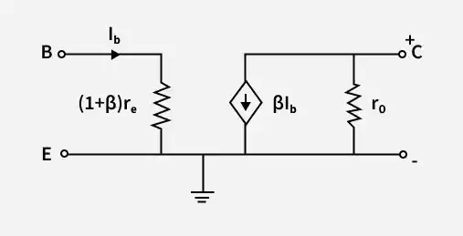
The emitter resistance is given by:
where:
V_T : Thermal voltageI_E : Emitter current at the operating (Q) point
The collector current is controlled by the base current and is expressed as:
In the T-model, a dependent current source represents the collector current, while an additional resistance
where
This model is widely used for analyzing common emitter and common base amplifier circuits.
Analysis of Common Emitter Transistor Using T-Model
For AC analysis of a common emitter amplifier, the transistor is replaced by its T-equivalent circuit and DC sources are short-circuited.
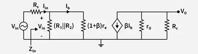
Input Impedance
The input impedance is:
Since
Output Impedance
The output impedance is given by:
Voltage Gain
The voltage gain of the amplifier is:
Using the T-model,
The negative sign indicates that the output signal is inverted with respect to the input.
Voltage Gain Considering Source Resistance
When the source resistance
Analysis of Common Emitter Transistor with Unbypassed Resistor
If the bypass capacitor
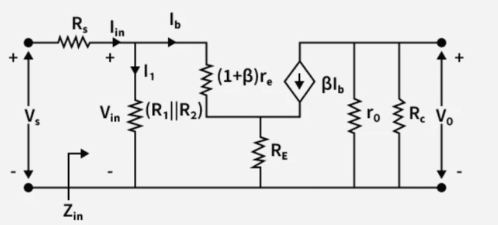
The presence of
Effects of Unbypassed Emitter Resistor
- Input resistance increases
- Voltage gain decreases
- Amplifier stability improves
Input Impedance
The input impedance becomes:
Output Impedance
The output impedance remains approximately:
Voltage Gain
The voltage gain is reduced due to the emitter resistance:
Voltage Gain Considering Source Resistance
When source resistance is included:
