

The basic current mirror has a limitation when very small output currents are required. To generate low currents, the reference resistor
- It is a modified version of the basic two-transistor current mirror in which an emitter degeneration resistor is added to the output transistor.
- This allows generation of very small output currents using moderate resistor values.
Need
In a basic current mirror:
I_{\text{out}} \approx I_{\text{ref}} - To obtain very small output current,
I_{\text{ref}} must also be small - Small
I_{\text{ref}} requires a very large reference resistor - Large resistors increase IC area and cost
Therefore, a better technique is needed to generate low currents efficiently.
Circuit Concept
In the Widlar current mirror:
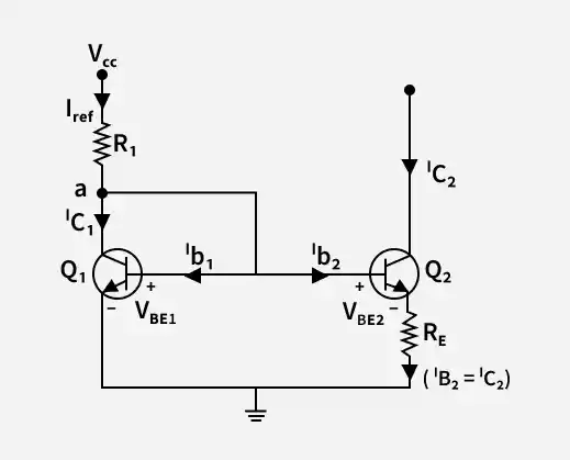
- The reference transistor remains unchanged.
- An emitter resistor
R_E is added to the output transistor. - This introduces emitter degeneration.
- The base-emitter voltages are no longer equal:
V_{BE1} \ne V_{BE2}
Because of this difference, the output current becomes significantly smaller than the reference current.
Mathematical Analysis
From the BJT current equation:
Taking the ratio of collector currents:
Taking natural logarithm:
Applying KVL in the emitter loop:
Since
Let:
Then,
This equation shows that very small output currents can be generated without using extremely large resistors.
Key Features
- Generates microampere-level currents
- Does not require very large reference resistor
- Uses exponential BJT characteristics
- Saves IC chip area
- Reduces noise due to emitter degeneration
Advantages
- Suitable for Low Current Generation : Efficient for microampere current sources.
- Reduced IC Area : Avoids very large resistor values.
- Improved Noise Performance : Emitter resistor reduces noise sensitivity.
- Better Thermal Stability : Emitter degeneration improves stability.
- Simple Modification : Only one additional resistor required.
Disadvantages
- Output Current Less Accurate Than Wilson Mirror : The current matching accuracy is lower compared to Wilson mirror due to limited output resistance.
- Reduced Output Voltage Compliance : The voltage drop across the emitter resistor reduces the minimum usable output voltage range.
- Slightly Increased Circuit Complexity : An additional emitter resistor makes the circuit slightly more complex than a basic mirror.
- Power Dissipation in Emitter Resistor : Some power is lost as heat in the emitter resistor during operation.
Applications
1. Biasing in Analog Integrated Circuits : Used to provide stable low-value bias currents inside analog ICs.
2. Low Current Reference Generation : Generates precise microampere-level reference currents.
3. Differential Amplifiers : Supplies controlled tail current in differential amplifier stages.
4. Operational Amplifier Bias Networks : Forms part of internal current biasing circuitry in op-amps.
5. Current Steering Circuits : Used in circuits where accurate low currents must be directed between branches.
