RS-1 is a watertight modular valve-based spy radio set,
developed at the start of the Cold War
– around 1948 – by the
USCentral Intelligence Agency (CIA)
and Radio Development and Research Corporation (RDR).
The first 3-piece units were fielded around 1950 and were used for
CIA field agent communication and for Stay-Behind Organisations (SBOs)
in Europe. From 1961 onwards, the set was also used by the US Army,
where it was known by the designator AN/GRC-109[1].
The RS-1 consists of separate modules that are each housed in a
water-tight container, allowing the radio to be stored under
harsh conditions for an extended period of time.
Each box has a lid with 4 screws at the corners and
a rubber gasket to protect it against water. The set is heavy and
can withstand air droppings and being buried in the ground;
ideal for stay-behind organisations.
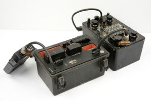
An example of a complete radio station is shown in the image on
the right. It consists of a T-784 transmitter,
a R-1004 receiver and a PP-2684 (or the small PP-2685) power
supply unit (PSU).
The CIA used the RS-1 spy set in many countries around the world,
such as South-East Asia, some countries behind the former Iron
Curtain (East-Europe), Vietnam, Tibet and Cuba.
With the CIA it lasted for nearly 15 years because of its proven
track record and reliability.
The Army used it even longer,
despite the fact that newer and lighter spy sets had meanwhile become available.
Development of the RS-1 started in 1948 by the CIA and Radio Development
and Research Corp. (RDR). It is believed that the first prototypes
and a small production batch were manufactured by RDR around 1950.
The bulk production was then taken over by Admiral Corp. The version
with clip-on case lids, was manufactured by Oklahoma Aerotronics, Inc.
The RS-1 was in production until 1964, but was used for several years
after that, in some cases well into the 1970s.
Depending on the intended application – agent or paramilitary use –
the RS-1 was succeeded by quite a few candidates, including the
RS-6, RS-69 (Delco 5300, AN/PRC-64), AS-3,
RS-49, RS-59, RS-100, RS-101
and TAR-224. Note however, that the RS-100 and
RS-101 sets were never produced in large quantities and were both
merged into the TAR-224.
RR-2 is a single-conversion super heterodyne receiver with 6 valves:
RF pre-amplifier (1T4), local oscillator/mixer (1L6), 2 x IF amplifiers
(1T4), AF amplifier (1U5) and a BFO (1T4).
The intermediate frequency (IF) is at 455 kHz.
The receiver can be crystal or VFO operated.
The image on the right shows an RR-2B receiver, which covers
3 to 24 MHz in 3 bands:
3 - 6 MHz
6 - 12 MHz
12 - 24 MHz
Transmitter RT-3
T-784
The transmitter is only suitable for CW (morse) and covers 3 to 22 MHz
in 4 bands. It has two valves: an 6AC7 for the crystal oscillator and
a 2E26 for the RF power amplifier.
The output power is 12-15W (at 3-15MHz) and 10-12W (at 15-22MHz).
Some transmitters have been modified with a socket for connection of a burst encoder.
Power Supply Unit RP-1
PP-2684
The RP-1 is the larger of the two power supply units. It can
power the RS-1 radio station from virtually any AC mains
voltage in the world.
In addition it contains a built-in power invertor, allowing the
radio to be powered by a 6V DC source such as a car battery.
It can also be used to recharge the 6V battery from
the mains.
The RS-1 can also be used in combination with the SSP-11
hand-crank generator, which is a modified version of the GN-58.
Power Supply Unit RP-2
PP-2685
The smaller RP-2 PSU has the same size as the RX and TX units.
It is suitable for connection to the mains only and does not
have a DC or battery input.
Note that the mains plug is made
of rubber, so that the two contact pins can be pressed together
in order to fit a variety of mains sockets.
Burst encoder CK-8
GRA-71
In order to avoid detection by enemy eavesdroppers, it was necessary
to be on the air as short as possible. The Army version of the RS-1
was therefore modified to allow an AN/GRA-71
burst encoder to be connected.
A limited number of CIA sets was also modified for use with this
burst encoder and the RT-3 transmitter was then renamed RT/D-3.
Some RS-1 sets came with a rectangular container with accessories and spares,
that is shown in the image on the right. The container has a watertight lid
that is held in place by two spring-loaded clip locks at the short sides.
When using the RS-1 in combination with the
AN/GRA-71 burst encoder described above,
the encoder has to be connected to the special socket, marked
KEYER, just above the internal morse key of the T-784 transmitter.
This socket is only available on modified T-784 transmitters.
Keyer socket (M10S)
The actual burst encoder of the GRA-71, the so-called KE-8B Keyer,
can be connected to the T-784 transmitter, using the
KA-3 Keyer Adapter as an interface. It converts the low-voltage
signals of the transistor-based GRA-71 into the high-voltage levels
of the valve-based T-784.
The transmitter is modulated by
switching the Anode of the Power Amplifier (PA) valve in the rithm
of the morse data. During transmission, the transmitter's oscillator
is kept running by an R/C timing circuit inside the Keyer Adapter.
The oscillator is turned off automatically approx. one second
after the last (morse) character has been sent by the burst encoder.
The Keyer Adapter also contains a stabilizer for the PA screen grid
voltage. Please refer to the circuit diagram of the Keyer Adapter
in the GRA-71 Depot Maintenance Manual for further information [C].
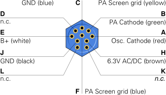
Shorting connector
If the T-784 transmitter has a socket for an external keyer and no
keyer is connected, a shorting plug should be inserted into socket J1.
Without this shorting plug, the transmitter will not work. The diagram
above shows the wiring of the shorting plug. There are two bridges:
A, B, L and E, K.
Designators
Originally, the set was called RS-1 by the CIA.
Around 1961 the US Army adopted the set for their special forces (DF)
and designated it AN/GRC-109.