PGFS-0201 is a versatile test device for
teletypewriters (teleprinters) and telegraphy networks,
developed around 1978 by Standard Elektrik Lorenz
(SEL) in Stuttgart (Germany). 2
It was also sold by Siemens in München.
It can simulate TW39 single- and double-current lines, as well as ED1000
tone modulated lines (FSK) with all tone frequency combinations,
in both simplex and duplex modes. It can also generate various test sequences.
The PGFS-020-3 also supports V.21.
The device is extremely compact for the many functions and features
it offers. It measures 230 × 222 × 92 mm (without the carrying handle)
and weighs slightly over 3.5 kg. It is powered from the 110/220V AC mains,
and simulates a teleprinter exchange (telex). A teleprinter can be connected
to the ADo8 socket3 or to the V.24 socket at the
bottom edge of the front panel.
All functions and features are available from the front panel, in the form of
toggle switches and LEDs. It can even display the number dialled from a
teleprinter connection device (TCD).
Note that this device is entirely built with discrete logic. It does not
have a microcontroller. The PGFS 020-2 was developed around 1978 by Siemens
or SEL, initially probably for internal use. It was followed in 1982
by the PGFS 020-3, which offers additional support for V.21 FSK tones.
The devices were built in small quantities,
for use in repair workshops and by approval authorities.
It was sold worldwide, as illustrated by the fact that the manual is
available in four languages [A].
PGFS is the abbreviation of Prüf-Gerät für
Fern-Schreiber (test device for teleprinter).
It is unclear whether the device was developed by Siemens or
by SEL. There are no markings on or inside the device or the
documentation, that allowed us
to identify the original equipment manufacturer (OEM).
Teleprinters with a different connector (e.g. a
Walzenstecker) can be
connected to the ADo8 socket
by means of a suitable adapter cable.
The image below shows the front panel of the PGFS 020-3.
At the right is an ADo8 socket for connection of the teleprinter
under test (DUT). For teleprinters with a different connector (e.g. a
Walzenstecker),
a suitable adapter cable should be used.
The the left of this socket are eight coloured test terminals, which are
connected in parallel to the pins of the ADo8 socket.
At the rear are the remaining connections plus two switches.
The receptacle at the center is used for connection to the mains.
It accepts a Euro-standard power cable.
The LEDs at the left edge of the front panel will show the selected
mains voltage and frequency.
NOTE —
Ensure that the TEXT switch at the front panel is in the middle position
before connecting the device to the mains.
At the left is a power outlet
(similar to a wall outlet) for powering the Device Under Test (DUT),
under control of the power switch to its right.
The 5-way 240° DIN socket at the right, allows the device to be connected
directly to a teleprinter line. In that case, the device is inserted between
the line and the teleprinter. When the switch LINE at the front panel is set
to the upper position, the teleprinter is connected directly to the line
via a 22Ω resistor.
The toggle switch in the upper right corner (fA), can be used to invert
the mark/space tones of the FSK signal (ED1000 or V.21), regardless the
setting of the fA/fZ switch at the front panel.
Standard selection
ED1000
FSK tones 500/700 Hz and 2250/3150 Hz
V.21
980/1180 Hz and 1650/1850 Hz (PGFS 020-3 only)
TW39
Current-based telegraphy
When the standard selection switch is set to (1) or (2),
The transmitted tones (i.e. the tones sent to the teleprinter)
can be inverted with the fA switch at the rear without
altering the setting of the fA/fZ switch at the front.
This works in ED1000 and V.21 modes:
f1
Regular tones
f2
Inverted tones
When in ED1000 or V.21 mode (standard selection set to 1 or 2),
the FSK tones can be made audible by enabling the speaker (LSP).
This also works when connected to the line.
ON
Speaker on
-
Speaker off
V.24 interface
At the lower edge of the front panel is a
25-way DB25 socket that can be
used for connection of a V.24 compatible teleprinter such as the Siemens PT80.
This switch has three settings:
V24
TX data is looped to RX data
-
Off
-
TX data is displayed on the meter
Interior
The device consists of four main building blocks:
Name
Designator
Description
1.
Main board
GRUND 562
PSU, relays, logic
2.
Mains sensing
NEKON 563
Auto-selection of mains voltage
3.
Tone/UART board
FREQ+KEN 564
Tone decoder, identifier, character generator, UART
4.
V.21 board
EDS-S 786
ED1000/V21 frequency selection
The main board is the largest PCB (GRUND 562). It is fitted at the bottom
of the device and holds the power supply unit (PSU), the control logic and
six large socketed relays. One transformer is fitted to the board, whilst a
second one is mounted to the right side panel of the enclosure. Fitted on
top of the main board – right at the centre – is a smaller board (NEKON 563)
that holds the mains power analysis circuit.
It is responsible for auto-selection of the mains voltage (110/220V).
At the top of the device is the Tone/UART board (FREQ+KEN 564). It holds the
FSK tone decoders, two character generators
(PROMs, one for 5-bit and one for 8-bit),
the identifier (call-sign generator) and the UART for the
V.24 interface.
It also holds discrete logic for driving the character
generators and the V.24 interface (RS232).
Note that this device does not have a microcontroller.
When we received the PGFS-020-3 featured here, it was bascially in working
order. However, the SEND/REC switch
at the front panel was broken, and five minutes
after turning the device ON, it tripped the earth leakage circuit breaker,
ending the excercise in a big bang:
mains filter blown.
There were also some smaller problems. The mains power indicator
was loose and was about to disappear into the device's interior.
In addition, the scale of the current meter had come off at one end
and blocked the instrument's needle.
It was decided to fix the smaller issues first. As this required the
front panel to be removed, we also removed the top and bottom panels
so that we could inspect the interior.
Whilst at it, we also took off
the side panels, so that the carrying handle could be removed.
It was seriously malformed and was considered an annoying feature.
Although the handle allows the device to be carried easily, it is
difficult to adjust and can only be used properly in one position,
with the surplus ends of the handle sticking out. As the device
will become a standard tool in our workshop, we tought we would be better off
without the handle.
With the handle out of the way, we took care of the upper left corner of
the front panel, shown from the inside in the image on the right. The
SEND/REC switch is a double-pole double-throw (DPDT) switch, mounted
just below the meter. As it is screwed into a treaded hole in the front
panel, it required the meter to be removed first.
This gave us a chance to take the meter apart
and glue the scale back in place. The switch was
replaced by a new one,
and the meter was refitted. Furthermore, the
power LED was reseated and its holder was fixated with
a drop of glue.
Next, we addressed the more serious problem of the
exploded mains filter.
Although it came with a loud bang accompanied by nasty smelling smoke
that lasted for hours, it didn't come as a surprise.
Mains filters of all sorts have a limited life expectancy,
due to ageing of their capacitors.
Over time, small scracks
appear in the sealing of the capacitors or in the filter's enclosure, as a
result of which moisture can enter the body.
Luckily, it is not as bad as it seems and can easily be fixed by
replacing the filter. Sadly though, there is no modern alternative
with the same form factor that will fit the limited space of the
densely populated interior of the PGFS 020.
Although it is possible to leave the filter out and bypass it with
two wires, this is not recommended.
The filter protects the circuitry and the outside world
against interferences and transients.
The problem was solved by replacing the
mains power receptacle by a
version with a built-in mains filter and fixed wiring.
Although it is larger than the original one, we managed to
fit it in the existing space.
For this, the hole in the rear panel had to be enlarged by 1 mm
and part of the mains wiring had to be reorganised.
Whilst doing this, we noticed that the
green loudspeaker wire was too short,
as a result of which the Tone/UART board could not be tilted down completely.
To avoid breaking the wire and to make future repairs more comfortable,
we extended the length of this wire.
Finally, the unit was reassembled and fully tested.
It is now fully operational again.
Problems
Carrying handle bended and uncomfortable
SEND/REC switch broken (mechanically)
Meter scale loose (blocks the needle)
Mains LED loose (dissappears into the case)
Mains filter broken (exploded)
Speaker wire too short
Fixed
Carrying handle removed
SEND/REC switch replaced
Meter scale fixated
Mains LED fixated
Speaker wiring extended
Mains power socket replaced by version with embedded filter and fixed wiring
At the right of the front panel is an
ADo8 socket for connection of
the teleprinter-under-test. It is wired in the same
way as a regular subscriber wall socket, with pins 1-4 are wired as per
telex standard. The bridge between pins 5 and 6 (optionally present in the
wall socket) is uder control of switch (5 6 ON) at the front panel.
A modern teleprinter uses it to sense that it is connected.
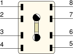
Below is the pinout of the when looking into the receptacle.
➤ More about the ADo8 socket
a1
TX a
b1
TX b
a2
RX a
b2
RX b
s
Shorting bridge to 6 1
s
Shorting bridge to 5 1
n.c.
unused
n.c.
unused
This is a bridge inside the socket (not the plug).
V.24 serial port
At the lower edge of the front panel is a 25-way socket marked V.24.
It is intended for connection of a teleprinter that supports the V.24
interface, such as the Siemens PT80. It is basically a partly implemented
RS232 interface.
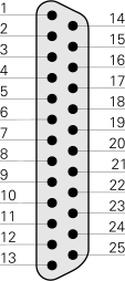
Below is the pin-out when looking into the socket. Note that only 8 pins
are used. Pins 3, 8 and 20 are interconnected by means of straps inside the
device. Pins 4 and 5 are both pulled high via a 1k resistor to +12V.
➤ More about V.24 (RS232)
2.
RX
from teleprinter to PGFS 020)
3.
TX
(from PGFS 020 to teleprinter)
4.
CTS
(+12V via 1k)
5.
RTS
(+12V via 1k)
6.
DTR x
7.
GND
8.
DCD x
20.
DSR x
The pins marked 'x' (6, 8 and 20) are interconnected.
Subscriber line
At the rear panel is a 5-pin 240° DIN socket
for connection of the
subscriber line. The device was supplied with a cable that fitted
this socket. The other end of the cable terminated in an ADo8 plug.
The subscriber line can be connected to the teleprinter
(i.e. the DUT) by setting the LINE switch at the front panel to ON.
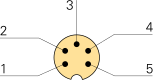
Below is the pinout when looking into the LINE receptacle.
German user manual by SEL 1
Prüfgerät für Fernschreiber PGFS 020-2, PGFS 020-3. SEL, June 1985. Incomplete [2].
This manual was published by SEL in June 1985 and appears to be the same
as the Siemens manual from May 1982 [B]. The available copy contains
the German text only, and no circuit diagrams.


 )
 )


