

A Use Case Diagram is a UML diagram that shows how users (actors) interact with a system and its functions (use cases). It provides a high-level view of system requirements and scope.
- Represents actors (users or external systems) and the use cases they interact with.
- Shows relationships between users and system functionalities, making requirements easier to understand.
Example: In an Online Banking System, actors such as Customer and Admin interact with use cases like Login, Check Balance, Transfer Funds, and Manage Accounts.
When to Apply Use Case Diagram?
Use case diagrams are used to understand, analyze, and communicate how users interact with a system.
- Requirements Gathering: Understand user needs and identify the system’s functions.
- Communication with Stakeholders: Provide a simple view of system functionality for both technical and non-technical users.
- System Design and Planning: Plan system features and workflows based on user requirements.
- Defining System Boundaries: Show what is inside and outside the system and identify the actors interacting with it.
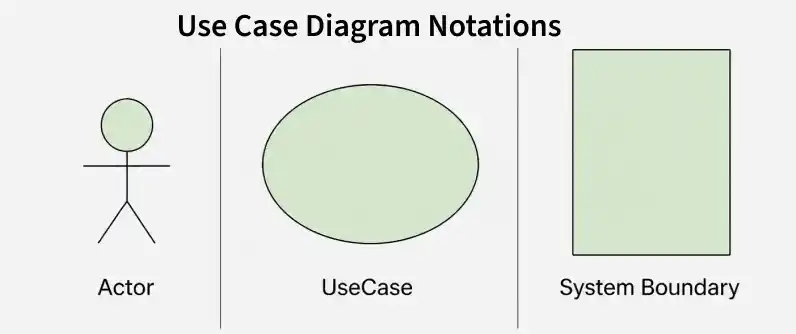
Use Case Diagram Notations
UML Notations provide a standard visual language to represent and communicate system design, architecture, and behavior clearly among developers and stakeholders.
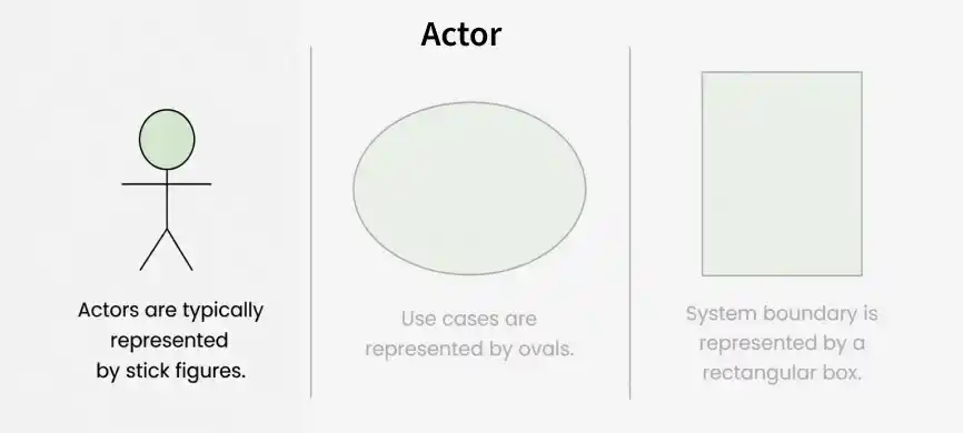
1. Actors
Actors are external entities that interact with a system to perform specific tasks or achieve goals. They can be users, other systems, or hardware devices that initiate or participate in use cases.
Example: In an ATM System, the Customer is an actor who performs actions such as Withdraw Cash and Check Balance.
2. Use Cases
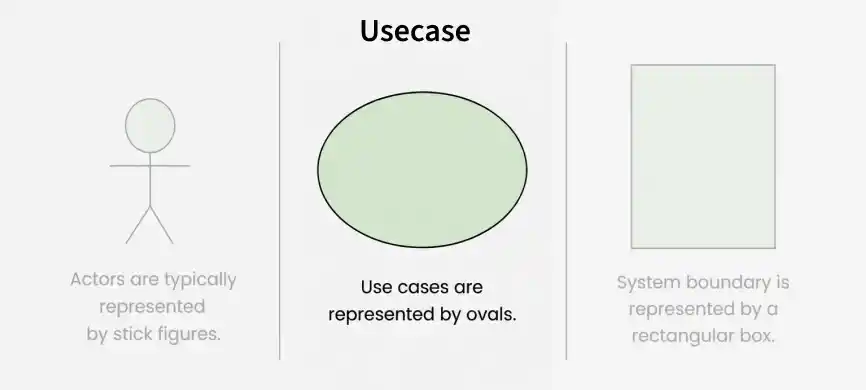
Use Cases represent specific system functionalities that help users achieve their goals. They show what the system does and are represented by ovals in a Use Case Diagram.
Example: In an Online Shopping System, "Place Order", "Track Delivery", and "Update Product Information" are examples of use cases.
3. System Boundary
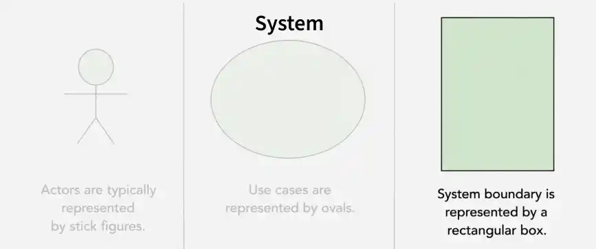
System Boundary defines the scope of the system and separates its internal functionalities from external actors. It is represented by a rectangle around the use cases.
Example: In an Online Shopping System, all use cases such as "Place Order" and "Track Delivery" are enclosed within the system boundary, while Customer and Admin remain outside as actors.
Use Case Diagram Relationships
In a Use Case Diagram, relationships play a crucial role in depicting the interactions between actors and use cases.
1. Association Relationship
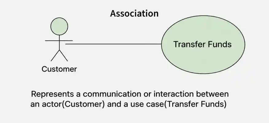
Association Relationship shows the interaction between an actor and a use case. It is represented by a line connecting the actor and the use case.
Example: Online Banking System
- Actor: Customer
- Use Case: Transfer Funds
- Association: A line connecting the "Customer" actor to the "Transfer Funds" use case, indicating the customer's involvement in the funds transfer process.
2. Include Relationship
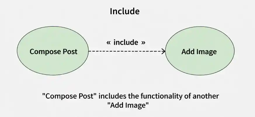
Include Relationship shows that one use case uses the functionality of another. It is represented by a dashed arrow pointing to the included use case.
Example: Social Media Posting
- Use Cases: Compose Post, Add Image
- Include Relationship: The "Compose Post" use case includes the functionality of "Add Image." Therefore, composing a post includes the action of adding an image.
3. Extend Relationship
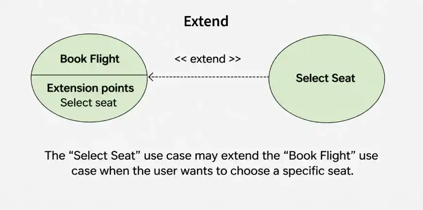
Extend Relationship shows optional or conditional behavior added to a use case. It is represented by a dashed arrow labeled “extend.”
Example: Flight Booking System
- Use Cases: Book Flight, Select Seat
- Extend Relationship: The "Select Seat" use case may extend the "Book Flight" use case when the user wants to choose a specific seat, but it is an optional step.
4. Generalization Relationship
Generalization Relationship shows an “is-a” relationship, where one use case is a specialized form of another. It is represented by an arrow pointing to the general use case.
Example: Vehicle Rental System
- Use Cases: Rent Car, Rent Bike
- Generalization Relationship: Both "Rent Car" and "Rent Bike" are specialized versions of the general use case "Rent Vehicle."
Use Case Diagram example(Online Shopping System)
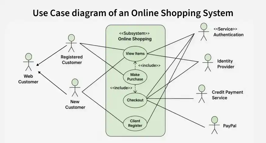
Let's understand how to draw a Use Case diagram with the help of an Online Shopping System:
- Actors
- Customer
Use Cases
- Browse Products
- Add to Cart
- Checkout
- Manage Inventory (Admin)
Relations
- The Customer can browse products, add items to the cart, and complete the checkout.
- The Admin can manage the inventory
The use case diagram of an Online Shopping System:
Common Use Case Diagram Tools and Platforms
Use Case Diagram Tools help create and design diagrams easily, support team collaboration, and improve overall efficiency.
- Lucidchart: Cloud-based and collaborative, with real-time editing, comments, and ready-made templates.
- Draw.io: Free and open-source, works online and offline, integrates with Google Drive and Dropbox, and supports many diagram types.
- Microsoft Visio: Part of Microsoft Office, supports Use Case and other diagrams, and provides many shapes and templates.
- SmartDraw: Easy to use, offers various diagram templates, and integrates with Microsoft Office and Google Workspace.
Common Mistakes while making Use Case Diagram
Avoiding common mistakes ensures the accuracy and effectiveness of the Use Case Diagram. Here are key points for each mistake:
- Adding too much detail can confuse people.
- Unclear connections lead to misunderstandings about system interactions.
- Different names for the same elements create confusion.
- Incorrectly using generalization can misrepresent relationships.
- Failing to define the system’s limits makes its scope unclear.
- Treating the diagram as static can make it outdated and inaccurate.
